Hydraulic Structures Guidelines
Overview
Hydraulic structures can include bridges, culverts, weirs, spillways, pumps or any facility that controls the water surface elevation and whose discharge can be specified by a rating curve or tables, or generalized culvert equations. Backwater effects upstream of bridges or culverts as well as blockage of a culvert or overtopping of a bridge can be simulated. A hydraulic structure can control the discharge between either contiguous channel or floodplain grid elements or cells that may be separated by several grid elements. For example, a culvert under an interstate highway may span several grid elements. In addition, flow can be exchanged between a floodplain element and channel element. A hydraulic structure rating curve equation specifies discharge as a function of the headwater depth h:
where:
a is a regression coefficient
b is a regression exponent.
More than one power regression relationship may be used for a hydraulic structure by specifying the maximum depth for which the relationship is valid. For example, one depth relationship can represent normal flow through a bridge and a second relationship can be used to simulate blockage with a zero coefficient for the height of the bridge low chord. Flow can also reverse and go upstream through a hydraulic structure. Hydraulic structures may include:
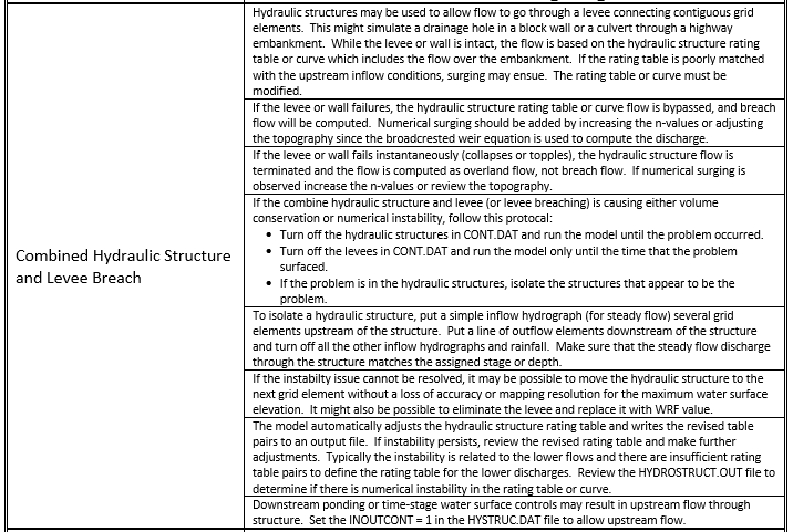
Broadcrested weir such as a berm or embankment (Figure 1);
Sharp crested weir such as a wall;
Channel side retention basin control weirs;
Spillways or outlet works from a dam (e.g. Ogee Weir);
Culverts;
Bridges;
Detention basin pumps;
Highway dip crossings;
Pumps
Figure 1. Broadcrested Weir Equation for Modeling Hydraulic Structure Flow Over an Embankment
By specifying a hydraulic structure rating table, the model interpolates between the depth and discharge increments to calculate the discharge. A typical rating curve will start with zero depth and zero discharge and increase in non-uniform increments to the maximum expected discharge or higher. In general, the rating table will be more accurate than the regression equation if the curve is nonlinear on a log-log plot of the depth and discharge. The rating table must be based on a reference elevation (Figure 2). Flow blockage by debris can be simulated by setting the discharge equal to zero corresponding to a prescribed depth. This blockage option may useful in simulating worst case mud and debris flow scenarios where bridges or culverts are located on alluvial fans. Blockage forces all the discharge to flow overland on the fan or floodplain surface.
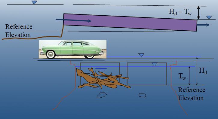
Figure 2. Levees are Depicted in Red and the River in Blue in the GDS Program
For a simplified storm drain system, multiple inflow nodes can be assigned to the same outflow element. This will enable the cumulative storm drain discharge at the outlet to be assessed without conduit flow routing. It is possible to assign a limiting conveyance capacity for the outlet node (Figure 3). This will curtail the inflow in subsequent downstream inlets. Once the conveyance capacity is exceeded, the discharge to the remaining downstream inlet nodes is zero.
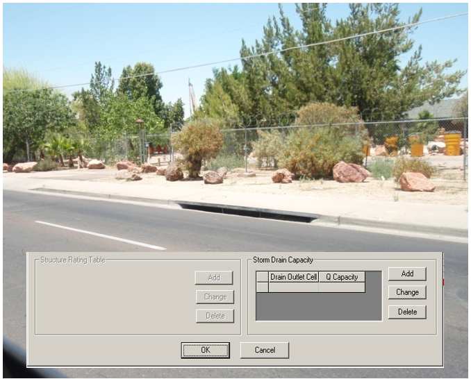
Figure 3. Multiple Storm Drain Inlets to a Single Outlet with a Conveyance Capacity Limit
Generalized equations for inlet and outlet control for round or rectangular culverts are available in the Pro model. The culvert discharge will be computed using equations based on experimental and theoretical results from the U.S. Department of Transportation procedures (Hydraulic Design of Highway Culverts; Publication Number FHWA-NHI-01-0260 revised May, 2005). This approach will replace the original model rating table or curve methods. The equations include options for box and pipe culverts and take into account different entrance types for box culverts (wingall flare 30 to 75 degrees, wingall flare 90 or 15 degrees and wingall flare 0 degrees) and three entrance types for pipe culverts (square edge with headwall, socket end with headwall and socket end projecting). The highlights of this new component are:
Computes discharge through box or circular pipe culverts for various entrance conditions.
Computes both inlet and outlet control and the transition between them.
No rating curves or tables required.
The data required for the generalized culvert equations include (Figure 4):
Length
Diameter
Rectangular Width
Type – Box or Pipe
Entrance Type (3)
Entrance Loss Coefficient
Roughness
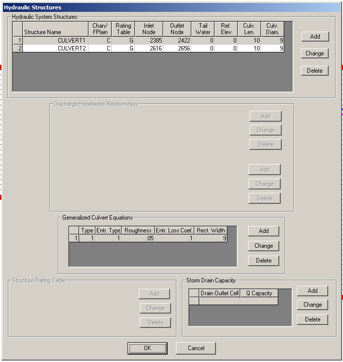
Figure 4. GDS Dialog Box for Entering the Generalized Culvert Data
Hydraulic structures may be used to allow flow to go through a levee. This might simulate a drainage hole in a block wall or a culvert through a highway embankment. The use of hydraulic structure in contiguous grid elements separated by a levee will preclude the discharge overtopping the levee or wall and the rating table or curve should represent flow through the structure and over the embankment. When the levee or wall fails the hydraulic structure flow is terminated and the flow between the contiguous grid elements is base on the levee breach. If the breach failure is instantaneous, the hydraulic structure flow is ceased and the flow reverts to overland flow.
Guidelines
Hydraulic structures pass flow across a grid element boundary and can connect two floodplain elements, two channel elements or a floodplain to channel element combination. The inflow and outflow elements of the hydraulic structure do not have to be contiguous. For example, several floodplain elements representing a highway embankment can separate the inflow and outflow cells of a culvert. If a two channel elements are joined by a hydraulic structure that are not contiguous, the intevening channel elements should no longer be designated as channel elements in the CHAN.DAT file. In this case the XSEC.DAT and CHANBANK.DAT should also be edited to remove the extra channel elements. For the floodplain (inflow) to channel (outflow) hydraulic connection, the channel element (left bank) must be listed in the CHAN.DAT file. It doesn’t matter if the inflow element is on the opposite of the river.
It is recommended that hydraulic structure inflow and outflow nodes be assigned to grid elements away from the project outflow nodes or grid system boundary to avoid water surface control or flow containment issues. It is also suggested that streets and ARF/WRF values be removed or left out of the inflow and outflow hydraulic structure elements. An warning or error message will be generated in the ERROR.CHK file if the conflicts are encountered.
Most hydraulic structures represent a hydraulic control. The flow is constricted through the structure or the entrance effects are less efficient than the normal depth flow reaching the structure from upstream. The flow decelerates through the structure and creates a backwater effect. This generally occurs over the entire range of flow to bankfull discharge. What can go wrong with a hydraulic structure rating table? When the hydraulic structure has a mismatched upstream depth or stage with the discharge through the structure this can cause surging in the either the inflow or outflow structure nodes. It is rare when a structure accelerates flow though it, but some steep box culverts or bridges with concrete aprons may result in higher velocities than those approaching the structure. In most cases, however, a rating table that accelerates flow through the structure is the result of low roughness or friction factors assigned to generate the table, lack of entrance coefficients, or inappropriate slope. When a rate table accelerates flow through hydraulic structure in the model, it pulls down the inflow node the water surface and conversely increases the outflow node storage. This changes the relationship between the headwater and tailwater can result in numerical surging through the structure (Figure 5).
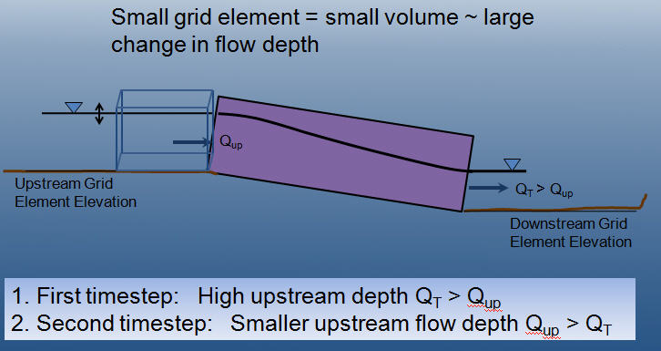
Figure 5. Hydraulic Structure Numerical Surging
It is possible to completely evacuate the hydraulic structure inflow node if the rating table poorly matches the upstream flow conditions at shallow depths. This occurs when the user is primarily interested in the 100-year event or bankfull discharges and neglets to assign sufficient detail to the lower portion of the rating table. In the following table, the user may be interested in discharges over 20,000 cfs, but what is the discharge at one foot?
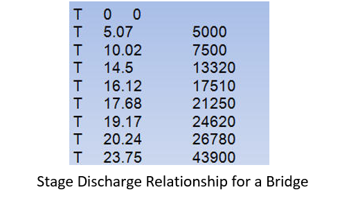
The discharge at 1 ft in the above table is 1,000 cfs. In almost any natural river channel, it is impossible to have discharge of 1,000 cfs with a depth of 1 ft above the thalweg. Typically the flow velocity would be on the order of 1 to 2 fps which would mean that the channel width would have to be 500 to 1,000 ft wide at 1 ft of depth. It is more reasonable for the discharge to be 100 to 300 cfs at one ft deep. More detail is necessary in the rating table so that numerically the water surface is not pulled down to accelerate the flow through the bridge.
Backwater, tidal control, river confluence and ponding downstream of hydraulic structures create a unique problem for numerical models. Hydraulic structure stage discharge tools and manuals such as HEC-RAS, culvert tables and other references establish discharge as a function of headwater depth or stage based on the assumption of steady, uniform flow. Flow conditions can significantly deviate steady flow when routing a flood event. The tailwater might be influenced by ocean levels or flood backwater effects from river constrictions. Two flow conditions that might will alter the floodwave routing are submergence and upstream flow. If it is reasonable certain that there is no potential for upstream flow, set the parameter INOUTCONT = 0 in Line S of HYSTRUC.DAT. In this case, the discharge Q is evaluate by the upstream headwater depth Hw regardless if the tailwater Tw surface exceeds the headwater surface elevation (Figure 6). A pump is also a hydraulic structure that may produce a discharge for a given stage.
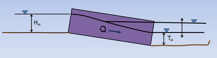
Figure 6. If INOUTCONT = 0, the Discharge Q is a Function of the Headwater Depth H:sub:`w` Regardless of the Tailwater T:sub:`w`
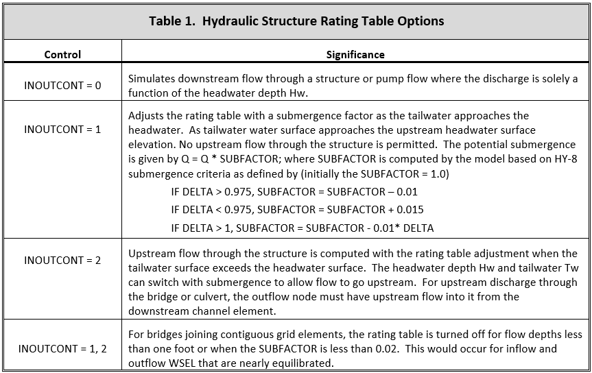
If a structure spans more than one channel element in a channel segment as shown in Figure 6 above, split the channel into two segments and assign the inlet node at the end of the first segment and the outlet node at the start of the second segment. As the tailwater increases in relation to the headwater, backwater or submergence may ensue and eventually flow may go upstream through a hydraulic structure (Figure 7). The effects of the relationship between the structure headwater and tailwater is controlled by the INOUTCONT parameter (0, 1, or 2) in the HYSTRUC.DAT file (Table 1). If INOUTCONT =2, headwater depth Hw and tailwater Tw can switch with submergence to allow flow to go upstream. The INOUTCONT parameter does not apply to the generalized culvert equations.
Modeling Pumps
The hydraulic structure rating table can be applied to simulate pump discharge by entering the stage (head) discharge relationship that is usually included with the pump manual. The head will be based on the invert elevation of the pump inlet that may be assigned to reference elevation in the S-Line of the HYSTRUC.DAT file. Generally, the pump will operate according to the stage-discharge relationship regardless of the tailwater condition or the higher elevation ground elevation of the outfall (outflow node). To simulate a pump, set INOUTCONT = 0 to model the discharge solely as function of the inflow node stage.
Numerical Instability
Hydraulic structures create an artificial control on the water surface elevation. This m2y cause a mismatch of the depth and discharge over a range flows resulting in surging upstream or downstream of the structure. Numerical instability can result in volume conservation problems, hydraulic structure discharge surging and slow simulation times. Most of the following hydraulic structure modeling problems and data issues are now checked automatically by the model and are listed in the ERROR.CHK at the termination of a simulation. At the outset, it might be expedient to run the model for a very short simulation time (SIMUL = 0.01 hr, TOUT = 0.01 hr). The model will start and stop in a minute or so and the ERROR.CHK file can be reviewed. This will allow the user to address any significant issues before proceeding with model development.
Virtually all the hydraulic structure runtime problems stem from a poor match of the rating table with the upstream flow conditions. This is primarily due to the underestimated roughness through the structure when developing the rating table using outside software such as culvert program or the HEC-RAS bridge routine based on a steady flow assumptions for both the headwater and tailwater conditions. When the tailwater elevation deviates from the expected headwater-discharge condition in the rating table, instability may ensue if the flow accelerates through the structure or if the tailwater varies with large fluctuations of the discharge. High maximum velocities (VELTIMEFP.OUT), rapidly varying discharges (HYDROSTRUCT.OUT), high or variable maximum water surface elevations are all evidence of numerical surging.
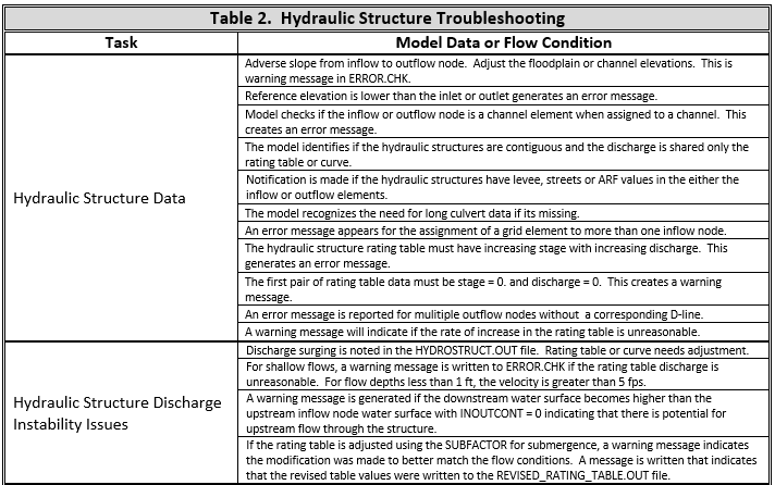
Hydraulic Structure Troubleshooting
General – Warning and Error Messages
Hydraulic structures can be a source of channel numerical instability when the rating curve or table discharge does not match the upstream flow. This occurs more frequently for low flow conditions. While FLO-2D can accurately replicate backwater effects, accelerating flow through a hydraulic structure is uncommon and will typically only occur with a concrete apron or channel. A rating curve or table that accelerates the flow through the bridge or culvert will pull down the water surface elevation in the inlet node. This will cause surging as the inlet node headwater drops until the discharge through the structure is low enough that the upstream flow will replenish the volume in the inlet node and start the surge cycle again.
Warning Messages are written to the ERROR.CHK file for the following structure issues:
Adverse slope between the structure inlet and outlet nodes;
Inlet or outlet nodes that also contain levee, streets or ARF’s;
Rating tables with a non-zero first pair of stage-discharge values (must be 0.and 0.);
The rate of increase in the rating table values is unreasonably high.
Error Messages are written to the ERROR.CHK file for the following conditions:
Reference elevation is lower than the inflow or outflow grid elevations.
Grid system Inflow or outflow nodes are also assigned as hydraulic structures.
Assignment of a channel element to more than one hydraulic structure inlet node.
Rating table must have increasing stage and Q.
The most frequent problem with application of the hydraulic structure routine is a rating table that is mismatched with an upstream flow condition. This occurs when the discharge through the structure defined by the rating curve or table is greater than the upstream inflow to the structure. This condition distorts the upstream water surface primarily by accelerating flow through the structure and pulling down the inlet headwater. Review the HYDROSTRUCT.OUT and HYCHAN.OUT files (use HYDROG program) for surging. High maximum velocities (VELTIMEC.OUT), rapidly varying discharges (HYDROSTRUCT.OUT), high or variable maximum water surface elevations are all evidence of numerical surging.
If surging is noted in the hydraulic structure hydrograph or the channel hydrographs near the inlet, the rating table or curve will probably need adjustment. The following conditions should be reviewed:
Shallow flows less than 1 ft in depth with velocity > 5 fps. Warning message
Downstream WSEL > upstream WSEL with INOUTCONT < 2 (potential upstream flow thru the structure). Warning message.
Rating table adjusted with SUBFACTOR. Warning message and revised table values are written to REVISED_RATING_TABLE.OUT file. The revisions listed in this file can be used to adjust the hydraulic structure rating table prior to the next simulation. Table 2 is a list of possible hydraulic structure issues and fixes.